10,14€
Avis des clients
- Tous les Commentaires (143)
- Image (22)
- Vidéo (0)
Trier par:
Avis uniquement de votre pays (France)
|
Afficher l'original
Une partie de la critique a été traduite automatiquement.
-
05/10/2021
Bon produit, mais ne peut pas fournir un courant de charge de 5A, à moins qu'il n'y ait un dissipateur de chaleur approprié sur les deux diodes et les deux mosfets. Cela peut aussi être dû au fait que RCS est plus grand que 0.04Ω. Dans tous les cas, le dissipateur de chaleur existant n'est pas correctement collé sous les composants, car il ne touche que partiellement certaines parties chauffées. Pire encore, le dissipateur de chaleur métallique touche les goupilles de certains autres composants et il y a danger de shorts et de dommages. En outre, dans mon unité, le double led est soudé dans l'autre sens, et en conséquence, quand il charge une batterie, le led bleu est allumé, et quand la batterie est pleine, le led rouge s'allume. Néanmoins, c'est un bon chargeur mppt. Je joins le profil de charge et son diagramme, tirés de la feuille de données CN3722.
Commentaires (1)Afficher l'original -
 MrBungleVIP1AU20/01/2019
This device works quite well at lower currents (< 3A). MPPT via panel voltage tracking seems to work quite well. I have mine outputting an almost consistant 10 Watts(2.8A @ 3.6v) into a 1s20p Lithium battery(nom. 3.6v, 45Ah) from a 12.5 Watt panel (21Voc, 17Vmp), so approx. 80% efficiency, even in 42 degree celcius ambient heat with panel temperature above 60 deg C !! (Australian summer). In 'cooler' summer weather (mid 20's) I get maybe an extra Watt out at mid day (~11W -ish). Although this is advertised as working up to 5A, even after extensive testing I was not able to get much above 4A with a 25Watt(measured) panel and very good heatsinking: I only get 15 Watts out (4.2A@3.6v) so efficiency at higher currents suffers badly (25W in, 15W out = ~60% efficiency) This item, as shipped, will NOT work with 1S lithium because the regulation voltage can only be adjusted down to ~6.5v, however, it is relatively easy to modify it for 1S operation. To do this, simply replace the 22k resistor (R7, marked 223, 0603 size) with something around 75k to 100k. I used an 82k resistor which alows me to adjust regulation from ~3.0v to ~9v. Note that the supplied heatsink itself is okay, but it is useless as supplied because it is mounted with a thick dob of silicone adhesive. This is because A) the current sense shunt resistor is thru-hole and protrudes, and B) the PCB tracks under it have exposed solder pads. Poor design/lack of forethought by whoever did the PCB layout!. Therefore, mounting the heatsink directly to the PCB would cause a short circuit. I have modified mine with heatsinks on the top side packages(Mosfets and Diodes), and also a heatsink with a drilled hole (to clear the shunt solder pad) un the underside using double-sided tape as insulation to avoid shorts with the board tracks. Not exactly ideal, but much better than as-supplied.
Commentaires (4)Afficher l'original -
15/12/2019
This is a buck only converter so the solar side voltage has to build up. Good product. Not really power point tracking, because the power point has to be set manually. Otherwise, good.
CommentairesAfficher l'original -
22/09/2022
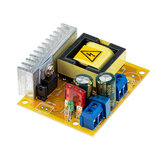
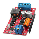
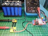
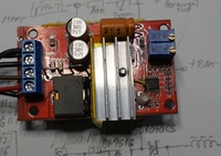
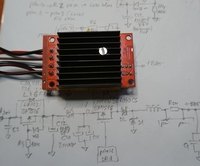
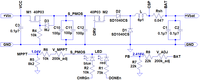
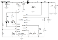
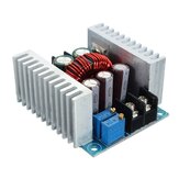
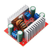
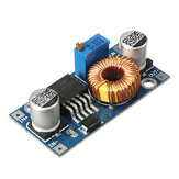
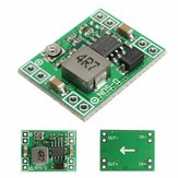
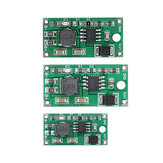
Le conseil arrive en Roumanie en provenance du CN dans environ un mois. Le régulateur MPPT avec CN3722 fonctionne bien. Je le recommande comme le MPPT le moins cher que j'ai trouvé (environ 9 USD); son fonctionnement est basé sur une tension d'entrée constante (appelée tension MPPT). Il peut être utilisé tel quel, mais j'ai préféré modifier son dissipateur thermique car il y a un risque de contact électrique, l'isolation est la peinture noire du dissipateur thermique seulement; J'ai fait un trou de 3 mm dans la connexion de masse sous D1 et mis un radiateur supplémentaire sur le dessus des PMOS et des diodes - les connecter avec une vis de 3 mm (photo 1 et 2) - sous le dissipateur thermique d'origine j'ai utilisé du ruban et de la pâte thermique. Le schéma de la carte peut être vu sur la figure 3 avec les noms des pins tirés de la fiche technique CN3722 (circuit typique - photo 4). Le réglage peut être fait directement avec le panneau solaire (SP) - régler V_MPPT au point où les LEDs clignotent sans batterie connectée; à ce point vous obtenez 1.04V (typique) sur le terminal MPPT, au-dessus de R5; vous pouvez ajuster V_MPPT également en fonction des caractéristiques du SP, à la tension de puissance maximale (environ 15..20% de moins que la tension en circuit ouvert) en utilisant une source supplémentaire (avec le courant limité à moins de 1A) réglée à la tension souhaitée. (ajustez pour obtenir 1.04V sur R5 et/ou au point de clignotement de LED, sans batterie). Avec la batterie connectée, vous pouvez régler la tension de fin de charge au point où vous obtenez 2.416V (typique) à la broche FB - sur R7, OU lorsque la batterie atteint la tension de fin de charge ajuster au point où les LED changent la couleur - du bleu au rouge ( dans mon cas - bleu charge, rouge est fin de charge (dans mon cas - normalement on s'attend à du rouge pour la charge...). J'ai testé le panneau avec une faible luminosité par jour nuageux (sans radiateur) avec un panneau solaire de 100W 22V, j'obtiens environ 20% plus de puissance par rapport au MPPT de la centrale XMUND XD-PS1. Je vais le tester aussi par une journée ensoleillée (avec dissipateur thermique maintenant) et j'ajouterai un commentaire.
Commentaires (2)Afficher l'original -
06/08/2023
arrêté du 22 juillet 2023 reçu le 6 août 2023. Mais la qualité de construction doit être améliorée... Chauffage à l'arrière en contact avec d'autres composants, ce qui peut conduire au court-circuit et au dysfonctionnement de l'appareil,
CommentairesAfficher l'original -
14/06/2022
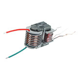
Le produit est arrivé cassé et était DOA. La bobine s'est cassée pendant l'expédition car il n'y avait qu'un sac en plastique mince et aucune protection. Voir les images. Je suppose que c'est un bon produit quand ça marche...
Commentaires (1)Afficher l'original -
IngvarVIP3SE24/11/2021
Il a été cassé à la livraison. Mal emballé sans aucun matériel d'emballage sous un emballage plus lourd (chargeur solaire Epever mppt). Une bobine s'était donc cassée lors d'une manipulation inévitable du colis.
Commentaires (2)Afficher l'original -
13/08/2023
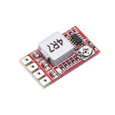
Commandé MPPT 5A Panneau Solaire Régulateur Contrôleur Batterie Chargeant 9V 12V 24V Commutateur Automatique 2 pcs sont arrivés comme convenu avec un petit retard, mais tout va bien. Je recommande l'achat!
CommentairesAfficher l'original -
 21/07/2023
Très bon produit. Expédition rapide.
CommentairesAfficher l'original -
11/05/2023
Livraison rapide en Grèce. Very good package.
CommentairesAfficher l'original


Show:
Vous pourriez être intéressé par
-
 10,60€
 -
7,37€
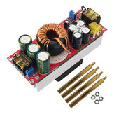
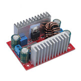
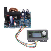
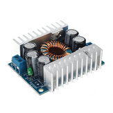
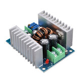
Module d'alimentation haute puissance Geekcreit® 400W DC-DC à tension constante et courant boost
-
11,66€
-
7,37€
-
6,45€
-
9,22€
-
8,48€
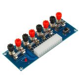
Module d'alimentation 12V à 3.3V/5V/12V par convertisseur de tension à sortie multiple DC-DC
-
14,84€
-
5,53€
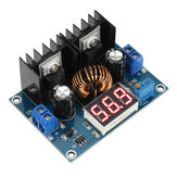
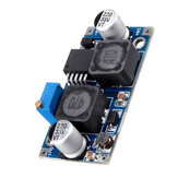
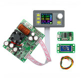
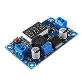
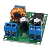
Module régulateur de tension LM2596 DC-DC ajustable avec affichage alimentation
-
6,99€
-
11,98€
-
7,37€
-
17,21€
-
8,29€
Module d'alimentation réglable LM2596 DC-DC à trois pièces avec affichage
-
7,37€
-
6,30€
-
62,73€
-
5,53€
-
5,31€
-
15,97€
-
28,64€
Module régulateur de tension LM2596 DC-DC réglable à pas vers le bas avec écran, 10 pièces
-
23,05€
-
16,97€
-
22,36€
-
35,06€
-
79,33€
-
5,16€
-
5,53€
-
13,83€
-
11,06€
-
61,76€
-
90,18€
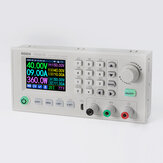
Alimentation à découpage régulée RIDEN® AC110V / 220V vers DC 68V 1200W pour RD6018
-
22,13€
-
18,03€
Module abaisseur réglable MP1584EN DC-DC BUCK mini 20pcs Entrée 4.5V-28V Sortie 0.8V-20V
-
4,60€
-
7,37€
-
5,53€
-
69,18€
-
6,45€
-
5,16€
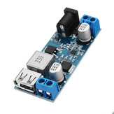
Module de charge de batterie lithium-ion USB avec carte d'intégration de charge et de protection
-
24,90€
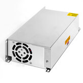
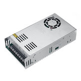
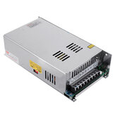
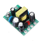
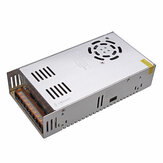
AC110V/220V à DC12V 20A 250W avec alimentation à découpage avec ventilateur 200*110*50mm
-
12,91€
-
3,40€
-
73,80€
-
15,67€
-
19,17€
-
8,29€
-
5,53€
Module de conversion de puissance abaisseur 24V / 12V à 5V 5A DC-DC
-
28,59€
-
37,12€
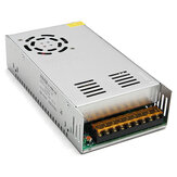
Carte de commande de l'alimentation à commutation Geekcreit® AC 110-240V vers DC 24V 17A 400W


recommendation for you
-
106,10€
-
8,29€
-
4,60€
-
7,37€
-
7,00€
-
21,21€
-
33,20€
-
10,60€
-
27,70€
-
9,58€
-
6,08€
-
7,92€
-
53,04€
-
63,65€
-
9,22€
-
16,97€
-
111,39€
-
37,12€